Pre-Engineered Building vs Conventional Buildings: Which is Better?

Over the years, building technology has been constantly developing and innovating from conventional building techniques to one of the most recent construction innovations, the pre-engineered buildings (PEBs) also known as prefabricated buildings. But which type of building structure is better? If you plan to build a new building project, it is important to consider some important parameters to help you decide which type of structural building technique is more cost-effective and sustainable.

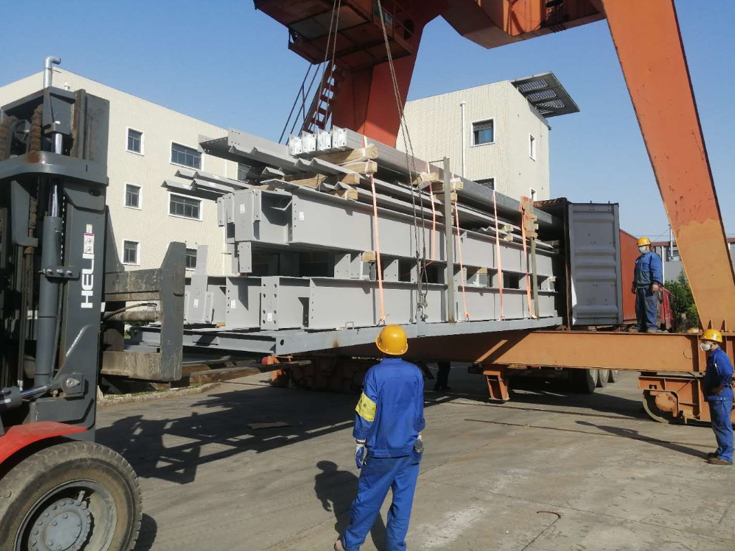
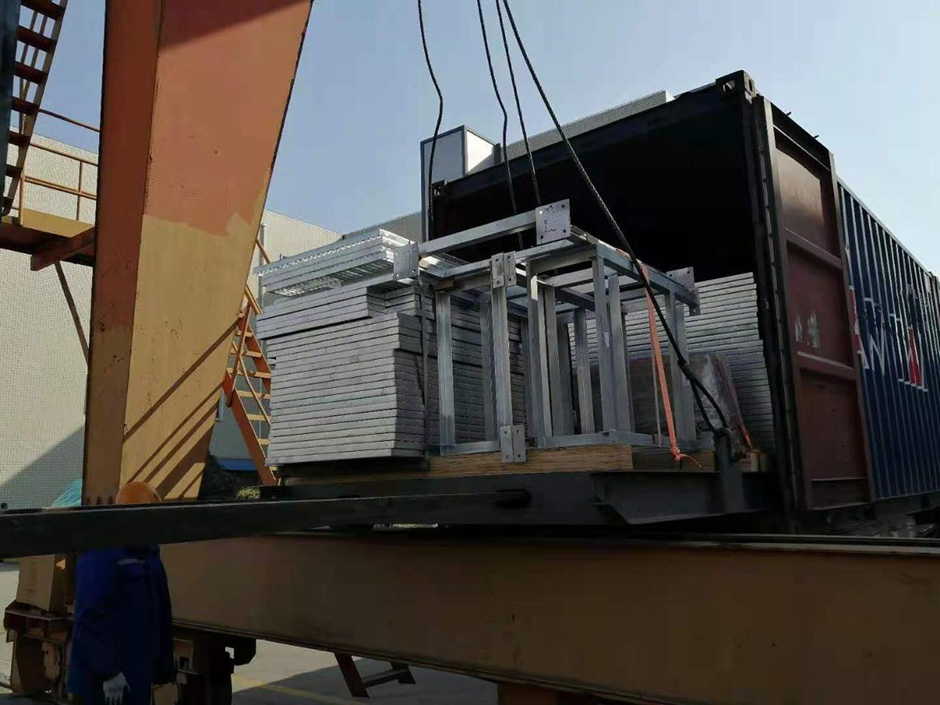
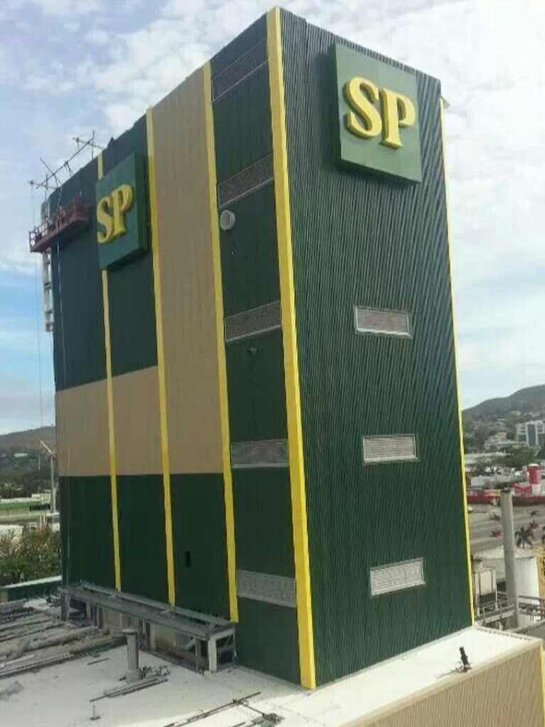
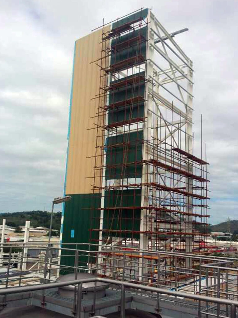
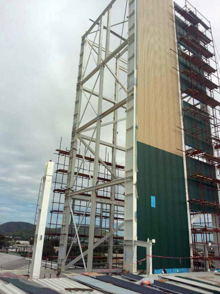
Pre-engineered buildings are built mostly in steel and are factory made, shipped to site, and bolted together. The rigid framing completes the roof, beams, and columns.

Then other exterior panels are assembled, along with structural elements and accessories. Pre-engineered buildings revolutionized the construction market with its built-up sections in place of conventional hot-rolled sections. Larger column-free area sets PEBs apart, compared to its conventional counterparts.

                                                                                    Pre-engineered Building Reefer Rack

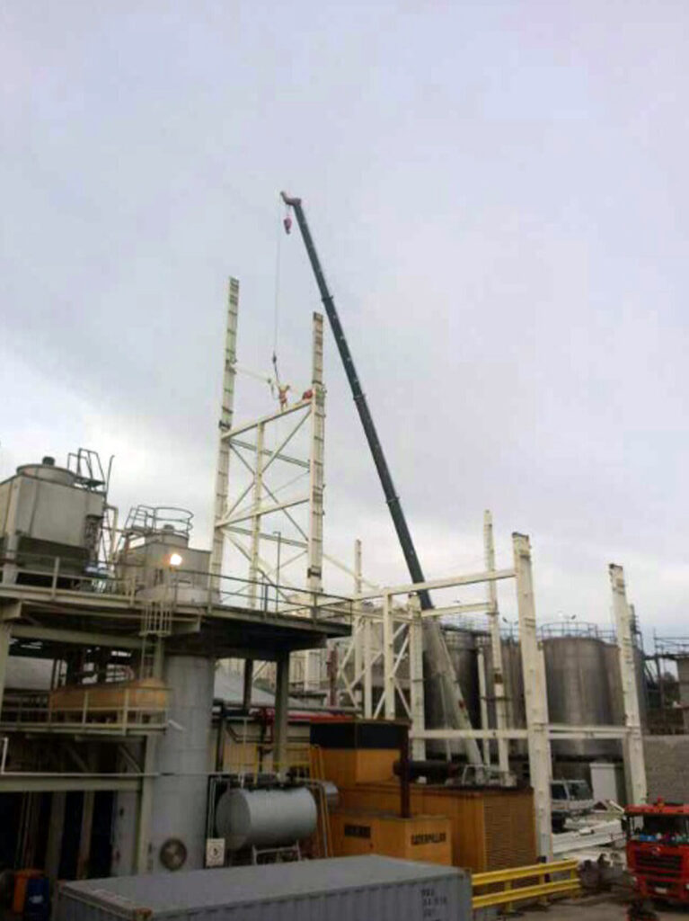
Conventional buildings on the other hand are traditional buildings consisting of steel, brick, and cement sections. These are fabricated and assembled at the site. Conventional building methods involve welding and cutting, which is done largely at the construction sites. A conventional building is designed from scratch, requiring substantial designing inputs, and detailing of the intricacies done by consultants.

Pre-fabricated Steel Buildings Installation on Site

Here we have differentiated between the pre-engineered buildings and conventional buildings on various parameters which will help you understand a proper comparison between the Pre-engineered buildings and conventional buildings.


Parameters
Pre-engineered Building
Conventional Building
Weight
About 20-30% lighter than the conventional buildings.
Structural members of the conventional buildings are Hot Rolled, which makes the building heavy-weight.
Structure
Primary members are tapered. Secondary Members are light weight & rolled framed ‘Z’ & ‘C’ sections
Primary members are hot rolled ‘I’ sections. Secondary members are ‘I’ & ‘C’ sections which are heavier in weight.
Design
Software based Standard designs that are replicable. The design of a PEB structure is efficient due to its integral framing system.
Partially automated designs with manual intervention. Requires more time and offers less precision in design.
Delivery Timeline
The components of the PEBs are designed at the factory, so it requires significantly shorter duration for its construction.
The delivery of conventional buildings are prolonged as compared to the PEB structures and can extend depending on complexity.
Foundation
Simple design and easy to build as the structural weight of the building is low, it requires a simple design foundation.
Substantial investment in foundation work as the weight of the building is greater, so it requires more cost for the construction of the foundation.
Erection Process
Easier, faster, and safer.
Labor intensive.
Seismic Resistance
The PEB offers good resistance against seismic actions due to its lightweight and flexible members.
Conventional Buildings cannot withstand seismic actions due to their heavy rigid members.
Sustainability
Reduced wastage and lesser impact on environment due to lean construction.
Wastage and energy consumption.
Flexibility
Future expansion is simple, easy, and cost effective as PEBs can be easily expanded in width as well as height by adding additional bays. Single supplier can coordinate changes.
Revisions or additions can be difficult and costly due to extensive redesign.
Performance
All components are specified and designed to act together as a system, for maximum efficiency, precise fit and performance.
Components are designed in general for possible use in many alternative configurations.
Accountability
Single source responsibility.
Multiple vendors involved.
Overall Cost
Lower cost due to the saving in design, manufacturing and on-site erection cost.
Applications
Best suited for industrial, infrastructures and warehousing projects.
Best suited for commercial establishments, institutional structures, industrial and residential applications.

Both pre-engineered and conventional buildings have their own advantages. Choosing the right kind of building structure depends on design requirements and materials your project demands. One must consider budget, safety, durability and maintenance before arriving at a decision.

                                                                    pre-engineered building components loading for shipping

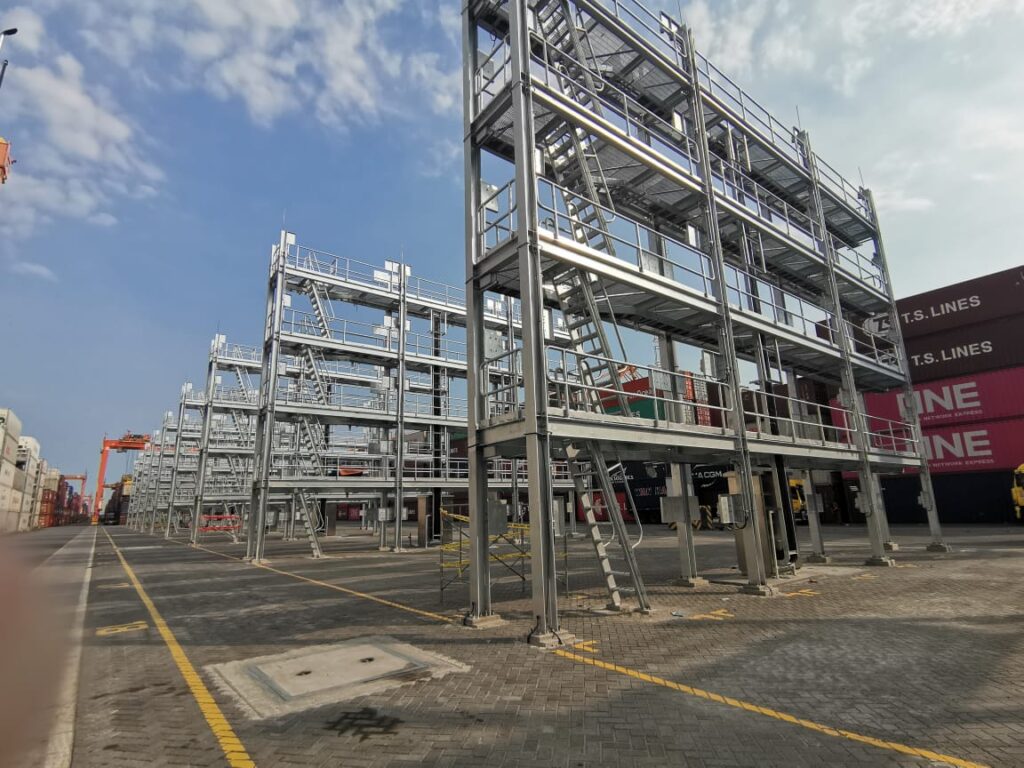
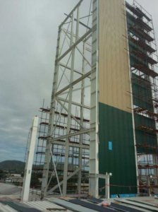
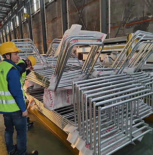
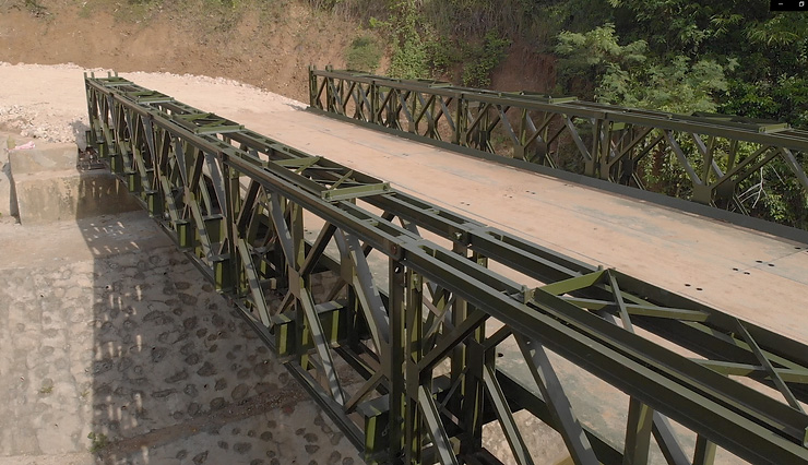
ESC can supply an assortment of prefabricated steel buildings also known as pre-engineered steel buildings (PEB), for a wide range of applications: from workshops, agricultural buildings, aircraft hangers, dealerships, industrial buildings, retail stores and more.

Utilizing steel is a sustainable, cost effective and very durable building material solution. It easily meets both aesthetic, technical requirements of a range of building codes around the world. ESC’s full service along with its roster of industry experts in engineering and manufacturing allows fabrication to follow all the way from the factory to site, providing hassle free solutions to its customers.

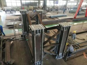
Other Steel Structure Fabrication Capabilities

Miscellaneous steel items for the Material Offloading Facilities
Bailey Bridge
Auxiliary bridge fabrication - Structural steel bridge component
Auxillary Structures
Wasterwater Treatment Plant

ESC is an expert steel structures fabrication company, Contact ESC to discuss your requirements.

Performance of Steel Buildings against Natural Disaster

Having sufficient knowledge of the latest and applicable design codes and standards enables a structural engineer to prepare cost-effective and safe design solutions for different structures. In essence, structures like concrete and Steel Buildings must be designed to resist the forces applied in various combinations/loading conditions. This is especially true for project sites where Natural Disasters such as storms/typhoons and earthquakes occur frequently.

Four (4) basic load cases are considered when designing Steel Buildings. The first two are predominantly applied along the gravity direction, while the succeeding loads are predominantly applied in the lateral direction. Further explanation of these basic load cases are as follows:

  1. Dead Loads (D)

         Dead loads are loads applied to the structure along the gravity direction. These include the self-weight of the structure (all permanent construction), and other materials permanently fastened onto the structure.

  1. Live Loads (L)

          Live loads are also applied along the gravity direction. These are loads are calculated depending on the structure’s occupancy. Live loads may vary at different locations of the structure. For example, the magnitude of the live load for an office space/room shall be different from that of the storage area of a particular building.

  1. Wind Loads (W)

         Wind loads are a combination of lateral and vertical loads applied to the contact surfaces of the building. Calculation of the wind load for a specific structure considers several factors. The structure’s geometry, the maximum wind speed at the project site, exposure category, gust effect, directionality and topography are just some of the major factors to be considered when designing Steel Buildings.

  1. Earthquake Loads (E)

           Earthquake/Seismic loads are forces calculated due to the seismic events the structure will be subjected to. Factors such as the nearest seismic source, the magnitude of the earthquake, soil type, and the type of seismic force-resisting system to be used are some of the factors to be considered in the calculation of the design earthquake loads for a structure.

Steel Buildings Natural DisasterSteel Buildings Natural DisasterSteel Buildings Natural Disaster

The basic principle of structural design is to select the best section of a structural member that can safely and economically resist the loads applied to it. These loads include various combinations of gravity and lateral forces in accordance with the provisions of the referral code. A structural steel section is considered economical if it can resist loads while maintaining an optimum self-weight (usually expressed in mass per unit length). An optimized self-weight of the section implies that lighter steel sections are required to be fabricated, and effectively lowers the material cost. At present, there are two design philosophies that are being used when designing steel structures. These are the Allowable Stress Design (ASD) Method, and the Load and Resistance Factor Design (LRFD) Method.

In the Allowable Stress Design Method, the steel section to be selected shall have cross-sectional properties (i.e., area and moment of inertia) adequate to resist the maximum applied loads under a permissible value. Applied loads may be in the form of compressive or tensile axial forces, shear forces, bending moments, and torsion. Each form of the applied load is compared to a permissible value of sectional strength.

This permissible value is referred to as the Allowable Strength. The Allowable Strength is defined by taking the Nominal Strength of the steel section and dividing it by a Factor of Safety (FS).

The value of FS varies for different types of loading conditions. For example, the safety factor for bending moment capacity shall be different from the factor of safety for shear capacity of the section.

In the Load and Resistance Factor Design, the sectional strength of a member under failure conditions is considered. The design process under LRFD is done by taking the sum of applied service loads and multiplying it with an individual load factor for each load type. The factored loads are then applied to the structure. Member size selection is determined by calculating for the strength of the chosen steel section and multiplying it by a reduction factor. To illustrate this better, the working principle behind LRFD is expressed as follows:

Factored loads are usually greater than the service loads, thus making the load factors greater than 1.0. The factored strength is always less than the nominal strength of the steel section, thus making the resistance factor less than 1.0.

Steel Buildings Natural Disaster At this point, the discussion focused on the determination of the sectional strength of a structural member. Despite satisfying the strength requirements from the applied loads, serviceability is also an important criterion in determining the right design for a structure. Two of the most common factors to consider in serviceability are the member deflection and the story drift. Depending on the governing design code, the deflection criterion is satisfied by taking the maximum deflection of a structural member due to the applied loads, and comparing it with the allowable deflection prescribed in the code. The allowable deflection is expressed as a fraction of the member’s unsupported length. This fraction also varies depending on the load condition being considered (e.g., D only, L only, D plus L).

Steel Buildings Natural Disaster

The second factor being considered when checking for serviceability is the drift of the structure. Drift is defined as the lateral displacement of the building when subjected to load combinations involving transient loads (wind and earthquake loads). In practice, the drift is calculated at the beam-column joints of the structure, per floor. The displacement of a joint on one story relative to one below it is called the inter-story drift.

For service load combinations involving wind loads, the permissible inter-story drift is valued as H/600 to H/400, where H is the story height. The permissible value is referred from Appendix CC (Serviceability Considerations) of ASCE 7-16 (Minimum Design Loads for Buildings and Other Structures).

For service load combinations involving earthquake/seismic loads, the seismic inter-story drift shall be not greater than 2.50% of the story height being considered for structures having a fundamental period of less than 0.70 s. For structures with a fundamental period of 0.70 s or greater, the seismic inter-story drift shall not be greater than 2.00% of the story height under consideration. The seismic drift is inelastic in nature due to the inelastic response of the seismic force-resisting system. The inelastic drift is calculated using the following equation:

Steel Buildings Natural DisasterWhere Δm is the inelastic drift, R is the seismic response modification factor, and Δs is the elastic drift. The prescribed drift limits were based on studies that determine the tolerance of both structural and non-structural elements of a uilding against lateral displacements under seismic events.

It is important that safety and economics are considered when designing Steel Buildings of any material type (i.e., reinforced concrete, structural steel, or a combination of both). These two factors should go hand in hand to come up with efficient building designs of varying occupancies. Adequate sectional strength and serviceability limits as prescribed by the local/governing structural codes must be observed by the Structural Engineer, especially for areas frequently struck by Natural Disasters such as earthquakes and strong typhoons. Strict implementation of these referral design codes ensures the optimum performance of the building while maintaining the safety and welfare of the general public.

For expert assistance on your steel building structures requirement, contact our team. You may email us at info@escsteelstructures.com or visit our website https://www.escsteelstructures.ph/ for further information