Having sufficient knowledge of the latest and applicable design codes and standards enables a structural engineer to prepare cost-effective and safe design solutions for different structures. In essence, structures like concrete and Steel Buildings must be designed to resist the forces applied in various combinations/loading conditions. This is especially true for project sites where Natural Disasters such as storms/typhoons and earthquakes occur frequently.
Four (4) basic load cases are considered when designing Steel Buildings. The first two are predominantly applied along the gravity direction, while the succeeding loads are predominantly applied in the lateral direction. Further explanation of these basic load cases are as follows:
Dead Loads (D)
Dead loads are loads applied to the structure along the gravity direction. These include the self-weight of the structure (all permanent construction), and other materials permanently fastened onto the structure.
Live Loads (L)
Live loads are also applied along the gravity direction. These are loads are calculated depending on the structure’s occupancy. Live loads may vary at different locations of the structure. For example, the magnitude of the live load for an office space/room shall be different from that of the storage area of a particular building.
Wind Loads (W)
Wind loads are a combination of lateral and vertical loads applied to the contact surfaces of the building. Calculation of the wind load for a specific structure considers several factors. The structure’s geometry, the maximum wind speed at the project site, exposure category, gust effect, directionality and topography are just some of the major factors to be considered when designing Steel Buildings.
Earthquake Loads (E)
Earthquake/Seismic loads are forces calculated due to the seismic events the structure will be subjected to. Factors such as the nearest seismic source, the magnitude of the earthquake, soil type, and the type of seismic force-resisting system to be used are some of the factors to be considered in the calculation of the design earthquake loads for a structure.
The basic principle of structural design is to select the best section of a structural member that can safely and economically resist the loads applied to it. These loads include various combinations of gravity and lateral forces in accordance with the provisions of the referral code. A structural steel section is considered economical if it can resist loads while maintaining an optimum self-weight (usually expressed in mass per unit length). An optimized self-weight of the section implies that lighter steel sections are required to be fabricated, and effectively lowers the material cost. At present, there are two design philosophies that are being used when designing steel structures. These are the Allowable Stress Design (ASD) Method, and the Load and Resistance Factor Design (LRFD) Method.
In the Allowable Stress Design Method, the steel section to be selected shall have cross-sectional properties (i.e., area and moment of inertia) adequate to resist the maximum applied loads under a permissible value. Applied loads may be in the form of compressive or tensile axial forces, shear forces, bending moments, and torsion. Each form of the applied load is compared to a permissible value of sectional strength.
![]()
This permissible value is referred to as the Allowable Strength. The Allowable Strength is defined by taking the Nominal Strength of the steel section and dividing it by a Factor of Safety (FS).

The value of FS varies for different types of loading conditions. For example, the safety factor for bending moment capacity shall be different from the factor of safety for shear capacity of the section.
In the Load and Resistance Factor Design, the sectional strength of a member under failure conditions is considered. The design process under LRFD is done by taking the sum of applied service loads and multiplying it with an individual load factor for each load type. The factored loads are then applied to the structure. Member size selection is determined by calculating for the strength of the chosen steel section and multiplying it by a reduction factor. To illustrate this better, the working principle behind LRFD is expressed as follows:
![]()
Factored loads are usually greater than the service loads, thus making the load factors greater than 1.0. The factored strength is always less than the nominal strength of the steel section, thus making the resistance factor less than 1.0.
 At this point, the discussion focused on the determination of the sectional strength of a structural member. Despite satisfying the strength requirements from the applied loads, serviceability is also an important criterion in determining the right design for a structure. Two of the most common factors to consider in serviceability are the member deflection and the story drift. Depending on the governing design code, the deflection criterion is satisfied by taking the maximum deflection of a structural member due to the applied loads, and comparing it with the allowable deflection prescribed in the code. The allowable deflection is expressed as a fraction of the member’s unsupported length. This fraction also varies depending on the load condition being considered (e.g., D only, L only, D plus L).
The second factor being considered when checking for serviceability is the drift of the structure. Drift is defined as the lateral displacement of the building when subjected to load combinations involving transient loads (wind and earthquake loads). In practice, the drift is calculated at the beam-column joints of the structure, per floor. The displacement of a joint on one story relative to one below it is called the inter-story drift.
For service load combinations involving wind loads, the permissible inter-story drift is valued as H/600 to H/400, where H is the story height. The permissible value is referred from Appendix CC (Serviceability Considerations) of ASCE 7-16 (Minimum Design Loads for Buildings and Other Structures).
For service load combinations involving earthquake/seismic loads, the seismic inter-story drift shall be not greater than 2.50% of the story height being considered for structures having a fundamental period of less than 0.70 s. For structures with a fundamental period of 0.70 s or greater, the seismic inter-story drift shall not be greater than 2.00% of the story height under consideration. The seismic drift is inelastic in nature due to the inelastic response of the seismic force-resisting system. The inelastic drift is calculated using the following equation:
![]()
 Where Δm is the inelastic drift, R is the seismic response modification factor, and Δs is the elastic drift. The prescribed drift limits were based on studies that determine the tolerance of both structural and non-structural elements of a uilding against lateral displacements under seismic events.
It is important that safety and economics are considered when designing Steel Buildings of any material type (i.e., reinforced concrete, structural steel, or a combination of both). These two factors should go hand in hand to come up with efficient building designs of varying occupancies. Adequate sectional strength and serviceability limits as prescribed by the local/governing structural codes must be observed by the Structural Engineer, especially for areas frequently struck by Natural Disasters such as earthquakes and strong typhoons. Strict implementation of these referral design codes ensures the optimum performance of the building while maintaining the safety and welfare of the general public.
For expert assistance on your steel building structures requirement, contact our team. You may email us at info@escsteelstructures.com or visit our website https://www.escsteelstructures.ph/ for further information
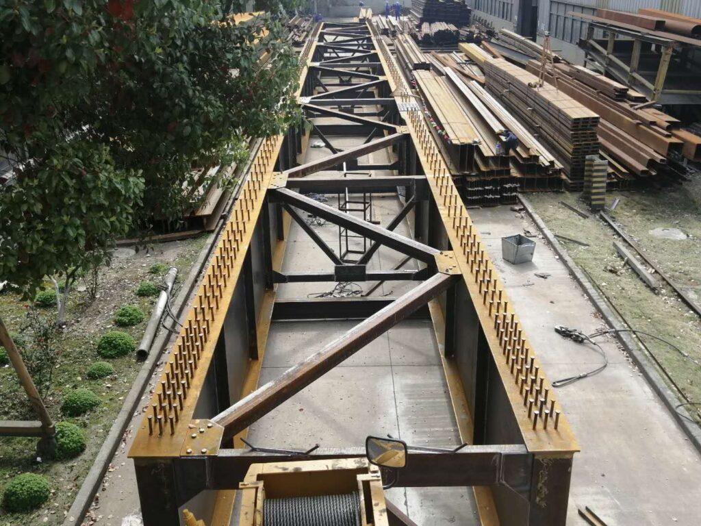

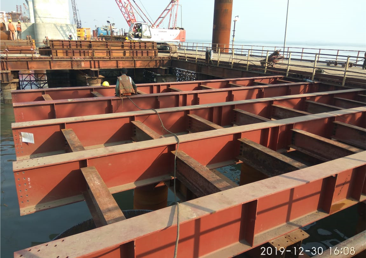
 Load-bearing capacity of a truss bridge depends on the framework of its superstructure composed of interconnected steel elements forming triangular units. The purposeful orientation of each individual steel member contributes to the efficiency of the truss to perform in tension, compression, or both as a result of dynamic loads.Trusses also serves as beam or component in composite decks, as arch bridge stringers, as cantilever beams, or as girders to cable-stayed Bridges. They are widely applied in foot-Bridges, demountable Bridges, gantries, and railway Bridges of over 50m span.
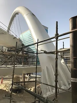
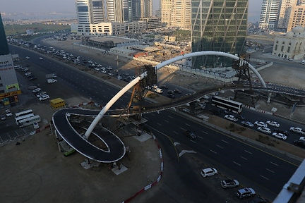
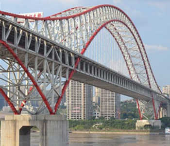 A ‘through arch bridge’ is also known as a ‘half-through arch bridge’ or ‘through-type arch bridge’. An arch structure which can be a steel truss, plate box girder, steel I-beam, or reinforced concrete section, supports the bridge deck. The deck can be supported on struts, sit on top of the arch, or suspended from the arch by tension cables. Steel arches act primarily in compression. Variation of this bridge type is the ‘tied-arch’ or ‘bow string arch bridge’. The deck hangs from the arch above it and acts as a tension tie. Arch Bridges are well suited to abridge wide waterways or wherever foundation works are difficult to construct or establish. Aside from being architecturally attractive, these Bridges are relatively cheaper and flexible. Photo credit:
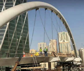
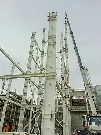
 Cable-stayed bridge involves towers or pylons where high-tension cables are anchored to support the deck girder at intervals. The cables or stays run directly from the tower throughout the center or both sides of the deck resembling a fan-like pattern. This type of bridge is an optimum solution for spans longer than Cantilever Bridges but shorter than Suspension Bridges. Recent engineering advances have made it possible to extend the effectiveness of Cable-stayed Bridges up to spans of over 1 kilometer. The anchor towers, which can be in the form of A-frame; H-frame; or a column, works in compression. The deck girders sustain compression and bending stresses.Photo credit: